![]()
G4BAO.COM
Microwave Amateur Radio Station, Waterbeach. 8km North Of Cambridge JO02cg
To Contact me:
Skype johng4bao
E-mail john at g4bao dot com
QTHR
Downloads and Bodger's Guides
Projects
A 9cm transverter using an Ionica receive converter and the "big board"
Modifications to the scavenged boards
On the upconverter board, locate the two double-PIN diode attenuators. The diodes (4) are marked "E4". As they stand they are set to maximum attenuation as they have no voltage on them You will either have to connect up to the 10 V rail to fully forward bias the diodes, or remove the diodes and bridge the RF tracks. I did the former.
Unfortunately the post- first mixer IF filter (the 4mm square silver component just above and to the left of the first mixer does is too low in frequency to cover 958MHz. You will have to remove it using a hot air gun or your wife's kitchen hotplate :-) and replace it with either a 958MHz helical filter or another SAW filter.
Fortunately the Ionica home unit (the infamous "Pizza box") has an identical sized filter in it that covers 958MHz. The Pizza boxes have been seen at rallies for a few pounds. This filter fits the upconverter board exactly.
Once you've done these mods,you should be able to connect up and get the unit working.
A note on mechanical construction
Fit the upconverter in either a tinplate or diecast box, and it is important that you solder vertical screens to the board where the gold borders are, or you will get a problem with (2442+814)3256MHz leaking in to the output. Get your unit checked on a spectrum analyser before you go on air!
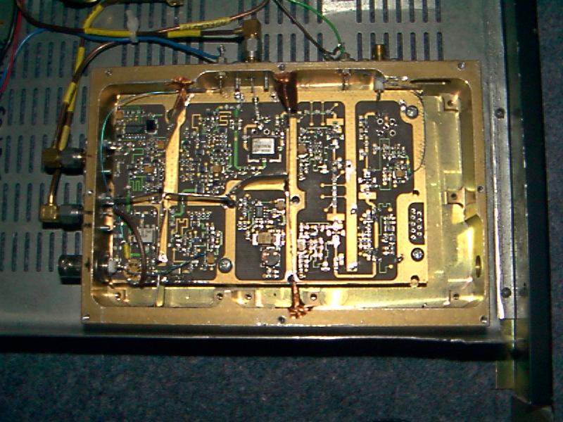 My
upconverter
My
upconverter
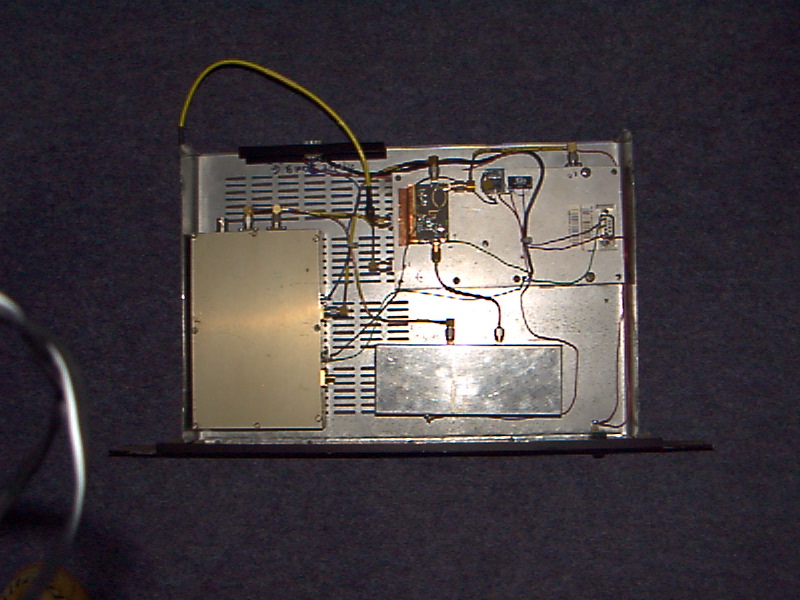 My completed
transverter
My completed
transverter