![]()
G4BAO.COM
Microwave Amateur Radio Station, Waterbeach. 8km North Of Cambridge JO02cg
To Contact me:
Skype johng4bao
E-mail john at g4bao dot com
QTHR
Related links
Projects
A 34Watt 3400 MHzs PA using Surplus Ionica units. - Part 3 the Power Supply
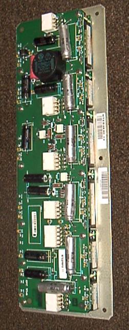
Included in the Ionica base station is a quite beautiful
multi output power supply consisting of six Nemic-Lambda
PH series 48 volt input switch mode modules with associated control
circuitry. A representative circuit for the 9.5V supply is on GM4ISM’s
excellent website. Nevertheless, I found I had to directly connect V+ to
S+ and V– to S– before the 9.5 V supplies would work rather than via 4k7
resistors as shown. The unit has three 12 volt, 8 amp modules. These are
already trimmed to 9.5V, one for each of the PAs , along with two more 12V
and a 5V supply that the PA needs. All the supplies are isolated so you
can use them as + or - supplies You just need an unregulated supply
between 35 and 50V at around 4 Amps to drive the whole PA.
One 9.5
volt module is used for each of the two PAs in this design. To
enable the 9.5 volt modules, you can either put +12V on the PSU enable
point, or simply disconnect the 560 ohm resistor from the collector and
ground with an open collector active low PTT line. The 12 and 5 volt
supplies are permanently enabled.
Connecting Up
The six white connectors (top view, with big round inductor to the right), pin out shown below) and the various test points give access to the required supplies as below.
| Function | Pins | |
| 48V input J1 | 1,2 = +48 | 4,6 = -48 |
| 9.5V 8A outputs J2,3 and 4 | 1,3,5 = -9.5V | 2,4,6 = +9.5V |
| +12V output J5 (has 10 pins) | 3 = +12V |
5, connect to 0V |
| -12V output J6 | 3 = 0V | 5 = -12V |
| +5CV logic high | TP12 = 0V | TP13 = +5V |