![]()
G4BAO.COM
Microwave Amateur Radio Station, Waterbeach. 8km North Of Cambridge JO02cg
To Contact me:
Skype johng4bao
E-mail john at g4bao dot com
QTHR
Downloads and Bodger's Guides
Projects
Recycling Andrew Corporation 900MHz Power Amplifier modules for 23cms
Now I had to resolder a single device in the centre where the pair were, but first I had to Dremel flat the ridge in the heat spreader between the devices, right where I wanted to put the single device.
Pain!
That done I returned the module to the hob, heated it up again, tinned the ground-flat area under the new single device, and dropped the device in place. Counted to 3, then pushed down with the tweezers on the device to make sure it bedded in the molten solder and removed it from the hob, keeping the pressure on it. The advantage of a glass topped hob is that you can slide the module off while keeping the pressure on it. Make sure the solder has set before taking off the pressure.
Now you can start hacking the unwanted tracks off and stick down the new matching lines cut out of adhesive copper foil.
Take great care to drill out the plated through holes that are left behind if you are going to stick copper foil over them. The sparks from 28volt, 10 amp power supplies can be quite spectacular.
The copper tape layout I ended up with is as follows
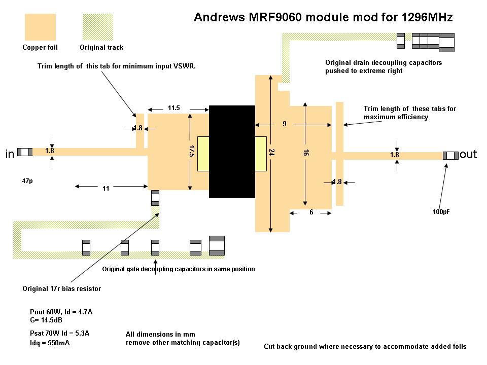
Figure 3 Layout and matching network in copper foil
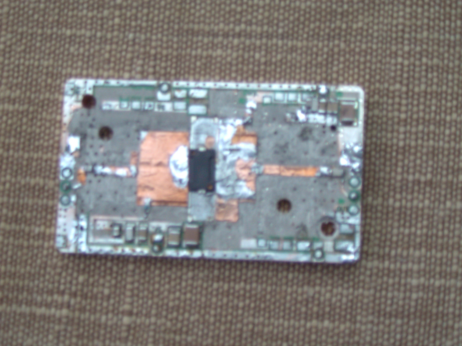
Figure 4 Modified output stage, not pretty , but effective
Alignment (either module)
Bolt the
module to a big heatsink. Connect up the input from your 23cms transmitter
via a SWR meter and the output to a power meter/ dummy load capable of at
least 70Watts. Connect the gate and drain bias, starting with ZERO volts
on the gate and connect the drain to 28volts via an ammeter on the 1 amp
range. VERY carefully increase the gate voltage until the device begins to
take current. This onset is very sharp, so be very careful. Set the drain
current for 350mA for the 9045 or 450mA for the 9060.
Switch the ammeter to the 10 Amp range, apply 0.5 watts drive and look at the input VSWR.
It goes without saying, I hope, that you must
DISCONNECT BOTH THE DRAIN AND SOURCE BIAS SUPPLIES BEFORE YOU START TRIMMING THE FOILS.
TRIM OFF NO MORE THAN HALF A MM BEFORE RE POWERING AND CHECKING
With a scalpel, trim the input tab until the vswr is less than 1.7:1 and look at the output power and current. Trim the output tabs for maximum power. Turn up the drive in 3dB steps to 2 Watts and check that the power increases about 3dB each time until it saturates. Now trim the output tab for minimum current consistent with maximum output power.
I got about 70 Watts out for the 9060 and 35 Watts for the 9045 at 5.3 and 3.3 Amps respectively. Check that the input VSWR is 1:5 or less and trim to suit. This is a bit of an iterative process so you may have to repeat the process a few times, and even extend the tabs again if you go too far!
Either of the modules on a suitable heatsink will be ideal for driving with a DB6NT or similar transverter, or a TS2000 with the power turned down a bit. This will give you a nice 70 or 35Watt PA. If you just want a stand alone single module amplifier, you can add a regulated bias circuit consisting of a 78L05 followed by a potentiometer to trim the quiescent drain current.
END